Amd AN9 32X User Manual
Browse online or download User Manual for Hardware Amd AN9 32X. AMD AN9 32X User Manual
- Page / 76
- Table of contents
- BOOKMARKS
- AN9 32X 1
- Contents 3
- 1. Introduction 5
- Internal I/O Connectors 6
- Rear Panel I/O 6
- RoHS Compliancy 6
- Miscellaneous 6
- Introduction 7
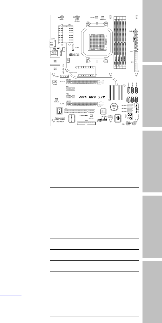
- 1.2 Motherboard Layout 7
- 2. Hardware Setup 9
- 2.3 Checking Jumper Settings 10
- Hardware Setup 11
- 2.4.1 ATX Power Connectors 14
- 2.4.3 FAN Power Connectors 16
- 2.5 Installing Hardware 17
- 2.6.2 Serial ATA Connectors 26
- 2.6.6 PCI Add-on Slot 28
- 2.7 Onboard Status Display 30
- 2.8 Connecting I/O Devices 32
- 3. BIOS Setup 33
- 3.1 µGuru 34
- Utility 34
- BIOS Setup 35
- 3.1.2 ABIT EQ 36
- Temperature Monitoring 36
- Fan Speed Monitoring 38
- 3.2 Standard CMOS Features 42
- 3.3 Advanced BIOS Features 45
- 3.5 Integrated Peripherals 49
- IDE Function Setup: 50
- 3.6 Power Management Setup 53
- 3.7 PnP/PCI Configurations 56
- 3.8 Load Fail-Safe Defaults 58
- 3.9 Load Optimized Defaults 58
- 3.10 Set Password 58
- 3.11 Save & Exit Setup 58
- 3.12 Exit Without Saving 58
- 4. Driver & Utility CD 59
- Driver & Utility CD 61
- 4.2 Realtek HD Audio Driver 61
- 4.4 Cool’n’Quiet Driver 63
- 4.5 USB 2.0 Driver 65
- 4.6 ABIT µGuru Utility 65
- 4.7 NVRaid Floppy Disk 66
- 5. Appendix 67
- 5-2 AN9 32X 68
- Appendix 69
- 5.2.2 Technical Support Form 74
- P/N: 4310-0000-18 76
- Rev. 1.00 76
Summary of Contents
Introduction AN9 32X Motherboard AMD Socket AM2 Hardware Setup BIOS Setup Driver & Utility CD Appendix User’s Manual About this Manual: This
To install this motherboard: 1. Locate all the screw holes onthe motherboard and the chassis base. 2. Place all the studs or spacersneeded on the c
Hardware Setup AN9 32X 2-3 2.3.1 CMOS Memory Clearing Header and Backup Battery The time to clear the CMOS memory occurs when (a) the CMOS data beco
CMOS Backup Battery: An onboard battery saves the CMOS memory to keep the BIOS information stays on even after disconnected your system with power so
Hardware Setup AN9 32X 2-5 2.3.2 Wake-up Headers These headers use a jumper cap to enable/disable the wake-up function. • PS2-PWR1: Pin 1-2
2.4 Connecting Chassis Components 2.4.1 ATX Power Connectors These connectors provide the connection from an ATX power supply. As the plugs from the
Hardware Setup AN9 32X 2-7 2.4.2 Front Panel Switches & Indicators Headers This header is used for connecting switches and LED indicators on the
2.4.3 FAN Power Connectors These connectors each provide power to the cooling fans installed in your system. • CPUFAN1: CPU Fan Power Connector •
Hardware Setup AN9 32X 2-9 2.5 Installing Hardware ※ DO NOT scratch the motherboard when installing hardware. An accidentally scratch of a tiny sur
4. Place the heatsink and fan assembly onto the retention frame. Match the heatsink clip with the socket mounting-lug. Hook the spring clip to the m
Hardware Setup AN9 32X 2-11 2.5.2 DDR2 Memory Slots This motherboard provides four 240-pin DIMM slots for Dual Channel DDR2 800 memory modules with
AN9 32X User’s Manual English, 1st Edition June, 2006 Copyright and Warranty Notice The information in this document is subject to change witho
To install system memory: 1. Power off the computer and unplug the AC power cord before installing or removing memory modules. 2. Locate the DIMM s
Hardware Setup AN9 32X 2-13 Two PCIE graphics cards installation (SLI Mode): To install two SLI-ready graphics cards under SLI Mode, you will need t
2.5.4 AudioMAX Connection Slot This slot provides the audio input/output connection over the rear I/O part through an add-on daughter-card. Find your
Hardware Setup AN9 32X 2-15 • FP-AUDIO1: This header provides the connection to audio connector at front panel. This header provides the front pane
3. Click “Disabled front panel jack detection”, and then click “OK” to confirm. S/PDIF Connection: In the motherboard package you can find one audi
Hardware Setup AN9 32X 2-17 2.6 Connecting Peripheral Devices 2.6.1 Floppy and IDE Disk Drive Connectors The FDC1 connector connects up to two
2.6.2 Serial ATA Connectors Each SATA connector serves as one single channel to connect one SATA device by a thin SATA cable. • SATA1~SATA6: Availab
Hardware Setup AN9 32X 2-19 2.6.3 Additional USB 2.0 Port Headers Besides the 4x USB 2.0 ports located at rear I/O part, this motherboard also featu
2.6.5 PCI Express X1 Add-on Slots These slots provide the connection of add-on cards that comply with PCI Express specifications. 2.6.6 PCI Add-
Hardware Setup AN9 32X 2-21 2.6.7 GURU Panel Connection Header This header is reserved for connecting ABIT’s exclusive GURU Panel. For more informat
Introduction Contents 1. Introduction... 1-1 Hardware Setup BIOS Setup Driver &
2.7 Onboard Status Display 2.7.1 POST Code Displayer This is an LED device to display the “POST” Code, the acronym for Power On Self Test. The comput
Hardware Setup AN9 32X 2-23 2.7.2 Power Source Indicators These indicators work as a reminding device to display the power status of this motherboar
2.8 Connecting I/O Devices • Silent OTES™: The Silent OTES™ (Silent Outside Thermal Exhaust System) is a device specifically designed to silently c
BIOS Setup AN9 32X 3-1 3. BIOS Setup This motherboard provides a programmable EEPROM so that you can update the BIOS utility. The BIOS (Basic Input/
3.1 µGuru™ Utility There are two setup menus in this µGuru utility. You may switch between these two by clicking the left or right arrow key on keybo
BIOS Setup AN9 32X 3-3 - Multiplier Factor This item displays the multiplier factor for the CPU you installed. - External Clock This item selects th
3.1.2 ABIT EQ Click right-arrow <→> key to switch from OC Guru setup menu to ABIT EQ setup menu: µGuru Utility V1.00 ABIT EQ ABIT EQ Beep
BIOS Setup AN9 32X 3-5 - Shutdown Enable Use <Space> key to enable system shutdown function. If the CPU/System/PWM’s temperature exceeds the s
- Beep Enable Use <Space> key to enable warning beeps function. If the voltage of corresponding element is higher/lower than the high/low limit
BIOS Setup AN9 32X 3-7 FanEQ Control µGuru Utility V1.00 ABIT EQ FanEQ Control ► CPU FanEQ Control Press Enter Item Help ►► ► SYS FanEQ Co
3.3 Advanced BIOS Features ...3-13 3.4 Advanced Chipset Features...
- Control Temperature High/Low These items set the high and low temperature limit that you want to do the fan speed control. - DC Fan Voltage High/
BIOS Setup AN9 32X 3-9 Click <ESC> key to exit this menu and move back to the main menu of “ABIT EQ”. Move the down-arrow key to the next item
3.2 Standard CMOS Features Phoenix – Award BIOS CMOS Setup Utility Standard CMOS Features Date (mm:dd:yy) Thu. May 25 2006 Item Help Time (hh:m
BIOS Setup AN9 32X 3-11 IDE Channel 1 Master/Slave, IDE Channel 3~8 Master: Click <Enter> key to enter its submenu: Phoenix – Award BIOS CMO
Head This item configures the number of read/write heads. Precomp This item displays the number of cylinders at which to change the write timing. Lan
BIOS Setup AN9 32X 3-13 3.3 Advanced BIOS Features Phoenix – Award BIOS CMOS Setup Utility Advanced BIOS Features Quick Power on Self Test Enable
Boot Up NumLock Status This item determines the default state of the numeric keypad at system booting up. [On]: The numeric keypad functions as numbe
BIOS Setup AN9 32X 3-15 3.4 Advanced Chipset Features Phoenix – Award BIOS CMOS Setup Utility Advanced Chipset Features K8<->NB HT Speed Au
DRAM Configuration: Click <Enter> key to enter its submenu. You may manually set the DRAM timing parameters through the following sub-items, or
BIOS Setup AN9 32X 3-17 3.5 Integrated Peripherals Phoenix – Award BIOS CMOS Setup Utility Integrated Peripherals ► OnChip IDE/RAID Function Press
Introduction 1. Introduction 1.1 Features & Specifications CPU • Supports Socket 940 AM2 Processor with 2GHz system bus using Hyper-Transport™ T
IDE Function Setup: Click <Enter> key to enter its submenu: Phoenix – Award BIOS CMOS Setup Utility IDE Function Setup IDE 1 Controller En
BIOS Setup AN9 32X 3-19 RAID Configuration: Click <Enter> key to enter its submenu: Phoenix – Award BIOS CMOS Setup Utility RAID Configurati
- USB Keyboard Support Select [BIOS] for the legacy operating system (such as DOS) that does not support USB keyboard. - USB Mouse Support Select [
BIOS Setup AN9 32X 3-21 3.6 Power Management Setup Phoenix – Award BIOS CMOS Setup Utility Power Management Setup ACPI Suspend Type S3(Suspend-To
Wakeup by OnChip LAN When set to [Enabled], you can remotely wake up a PC in Soft-Off condition via a LAN card that support the wake up function. Wak
BIOS Setup AN9 32X 3-23 - KB Power ON Password This item sets the password required in order to power on your computer. ※ Do not forget your passw
3.7 PnP/PCI Configurations Phoenix – Award BIOS CMOS Setup Utility PnP/PCI Configurations Resources Controlled By Auto(ESCD) Item Help X - IRQ Re
BIOS Setup AN9 32X 3-25 - IRQ Resources Click <Enter> key to enter its submenu: This item sets each system interrupt to either [PCI Device] or
3.8 Load Fail-Safe Defaults This option loads the BIOS default values for the most stable, minimal-performance system operations. 3.9 Load Optimized
Driver & Utility CD AN9 32X 4-1 4. Driver & Utility CD The “Driver & Utility CD” that came packed with this motherboard contains drivers
• 1x AudioMAX slot Internal I/O Connectors • 1x Floppy port • 1x UDMA 133/100/66/33 connector • 7x SATA connectors • 3x USB 2.0 headers • 2x IE
4.1 nVidia nForce Chipset Driver To install this driver: 1. Click on the [Drivers] tab in the installation menu screen. 2. Click the [nVidia nForce
Driver & Utility CD AN9 32X 4-3 4.2 Realtek HD Audio Driver To install this driver: 1. Click on the [Drivers] tab in the installation menu scre
4.3 Silicon Image 3132 RAID Driver To install this driver: 1. Click on the [Drivers] tab in the installation menu screen. 2. Click the [Silicon Ima
Driver & Utility CD AN9 32X 4-5 4.4 Cool’n’Quiet Driver To install this driver: 1. Click on the [Drivers] tab in the installation menu screen.
5. After the system restarted, open the “Power Options” from the control panel and choose the power scheme “Minimal Power Management” to enable Cool
Driver & Utility CD AN9 32X 4-7 4.5 USB 2.0 Driver ※ There is no need to install this driver for Windows 2000 with Service Pack 4, Windows XP w
4.7 NVRaid Floppy Disk If you lost or damaged the SATA Driver Disk that came with the package, use the NVRaid Floppy Disk to create another one. To i
Appendix AN9 32X 5-1 5. Appendix 5.1 POST Code Definitions 5.1.1 AWARD POST Code Definitions POST (hex) Description CF Test CMOS R/W functionality
25 Early PCI Initialization: -Enumerate PCI bus number. -Assign memory & I/O resource -Search for a valid VGA device & VGA BIOS, and put it i
Appendix AN9 32X 5-3 6B Program chipset registers according to items described in Setup & Auto-configuration table 6D 1. Assign resources to al
Introduction 1.2 Motherboard Layout AN9 32X 1-3
5.1.2 AC2005 POST Code Definitions POST (hex) Description Power On Sequence 8.1. Start power on sequence 8.2. Enable ATX power supply 8.3. ATX pow
Appendix AN9 32X 5-5 5.2 Troubleshooting (How to Get Technical Support?) 5.2.1 Q & A Q: Do I need to clear the CMOS before I use a new motherbo
Q: How to get a quick response for my request on technical support? A: Please carry out a simple troubleshooting before sending “Technical Support
Appendix AN9 32X 5-7 • Memory size: Type in the size of your memory module. Example: 512M* 4PCS • Memory configuration: Type in the memory configu
5.2.2 Technical Support Form 5-8 AN9 32X Country: First name: Last Name: Subject: Motherboard: BIOS Version: CPU: Memory brand: Memory size:
Appendix AN9 32X 5-9 5.2.3 UNIVERSAL ABIT Contact Information Taiwan Head Office UNIVERSAL ABIT Co. Ltd. No. 323, Yang Guang St., Neihu, Taipei, 114
P/N: 4310-0000-18 Rev. 1.00 http://www.abit.com.tw
1-4 AN9 32X
Hardware Setup AN9 32X 2-1 2. Hardware Setup In this chapter we will elaborate all the information you need upon installing this motherboard to your
Related products and manuals for Hardware Amd AN9 32X
 (62 pages)
(2 pages)
(64 pages)
(62 pages)
(50 pages)
(8 pages)
(3 pages)
(88 pages)
(45 pages)
(19 pages)
(80 pages)
(6 pages)
(62 pages)
(2 pages)
(64 pages)
(62 pages)
(50 pages)
(8 pages)
(3 pages)
(88 pages)
(45 pages)
(19 pages)
(80 pages)
(6 pages)
© 2020, manymanuals.com. All rights reserved. | 1.956 s |
 Manymanuals.com
 Manymanuals.de
 Manymanuals.fr
 Manymanuals.it
 Manymanuals.pl
 Manymanuals.cz
 Manymanuals.es
 Manymanuals-pt.com
Comments to this Manuals